ROBOT TOUR BLOG
Robot Tour was a Science Olympiad Event that I competed in from 2024 through 2026.
These are monthly blog posts about my experience with Robot Tour.
Chronological Development
September 2024
I began with a starter’s kit from Ward’s Science. It used a BBC Micro:bit, two DC motors, and an Inksmith k8 motor driver. I programmed it primarily with Microsoft Make Code. I experimented with some other MicroPython editors like Mu, but ultimately stuck with Make Code. The Inksmith k8 motor driver was at first hard to figure out because I could find very little documentation. I primarily used an extension for Make Code that was made by Inksmith. I grew rather frustrated with the limited control I had over the motors so I dug into how the library was made. I found the Github project and was able to figure out what pins to write to to control the motors. This gave the control I was looking for however it did not produce the intended results. Probably the biggest issue was that it would not go straight. A secondary issue was that since it used plain old DC motors
I had no way of tracking movement. My first invitational did not go well so I returned to the drawing board.
November 2024
Discouraged by the capabilities of the Inksmith motor driver and the kit motors, I decided to use an Encoder Motor from what I had learned while working on another event, Electric Vehicle.
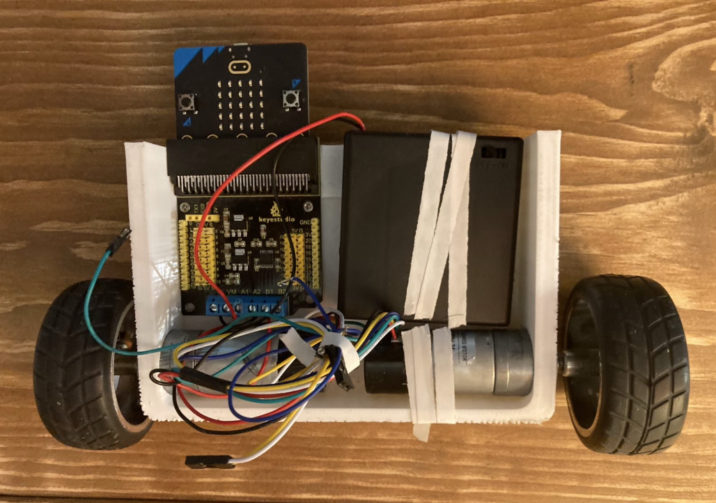
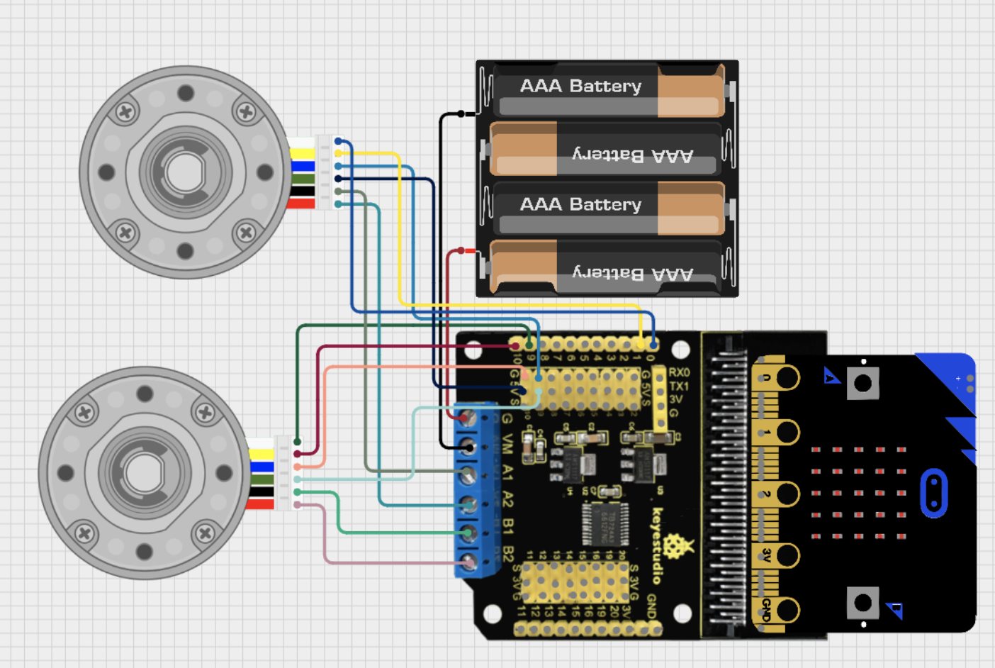
I at first tried an Arduino Uno R4 and an L298N motor driver with the encoders but landed on using the same Micro:bit paired with a Keystudio motor driver with the encoder motors:
This is the design I maintained for the rest of the 2024-2025 season.
The chassis changed slightly ending with this design:
The biggest issue with this new design was that while now I could successfully track
the distance traveled I was unable to move in a straight line. Performance of the robot
was also largely dictated by the voltage levels of the batteries making consistency hard
to achieve. I continued to tinker with it but this design is what stuck for the remainder of the 2024-2025 season.
September 2025
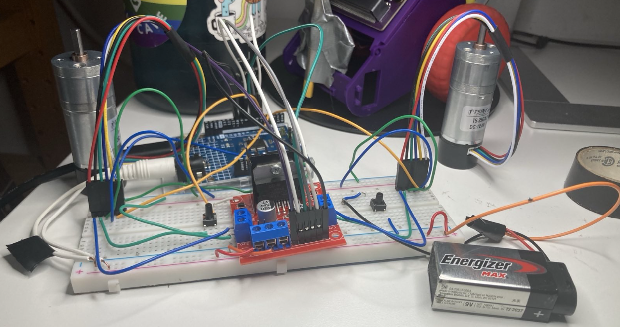
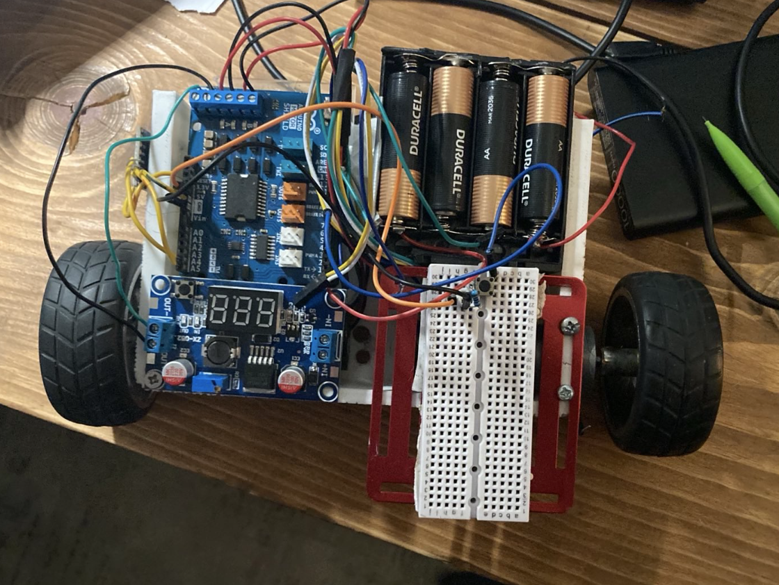
The new season of robot tour introduced a new bonus (object manipulation done by the robot) but was relatively similar to the 2024-2025 season. One big difference was that I was no longer soloing the project. My good friend Kaladin was now working with me on the project. We initially wanted to use something like a stepper motor instead of the encoders I had used last year. Since steppers seemed too difficult we landed on continuous servos. The components we used were an Arduino R4 with the Arduino Rev3 motor driver, two continuous servos, a buck converter, and 2 four-battery packs wired in series:
The idea with the buck converter was that we would regulate the voltage to the motors and thus end the unpredictable nature of the robot’s movement. However we misunderstood the behavior of the continuous servos. We thought that we could write a value (the change in orientation) e.g 720 degrees, to make the servo turn 2 rotations. This is not how continuous servos work. Continuous Servos have easily adjustable speeds so you can speed control without a motor driver. These obviously did not suit our needs.
Also this was actually the second chassis design of the season. The first one which has remained unpictured was destroyed after a battery incident. One of the batteries began leaking during testing and melted/corroded the aluminum frame. We treated the acid with a base to hopefully neutralize it, but the damage was done so we moved to the mostly 3d printed chassis you see above.
October 2025
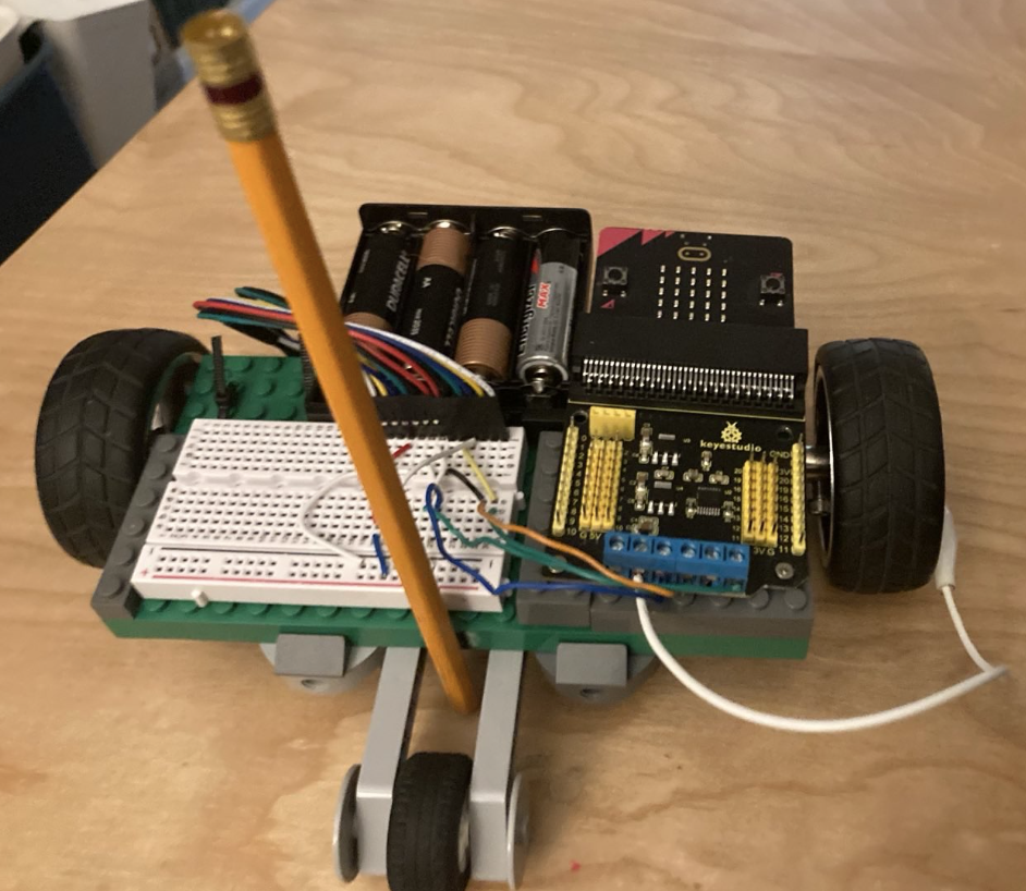
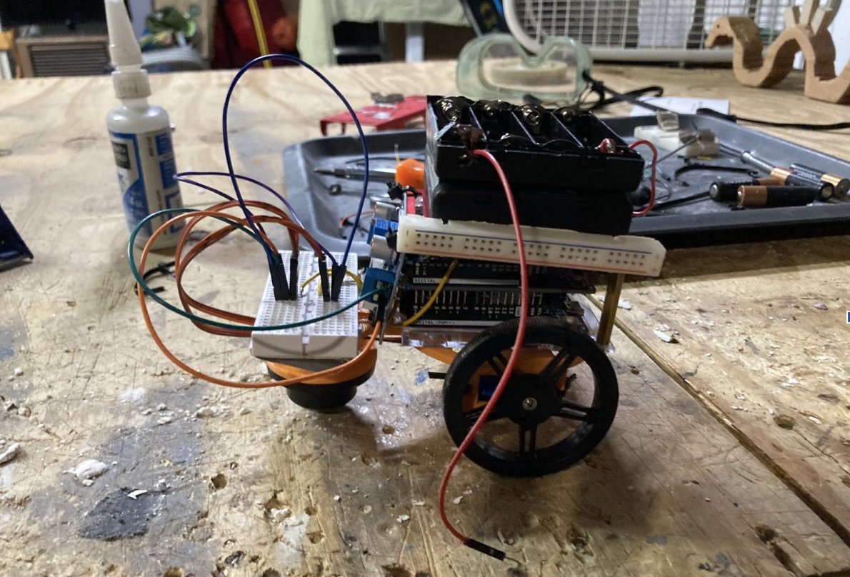
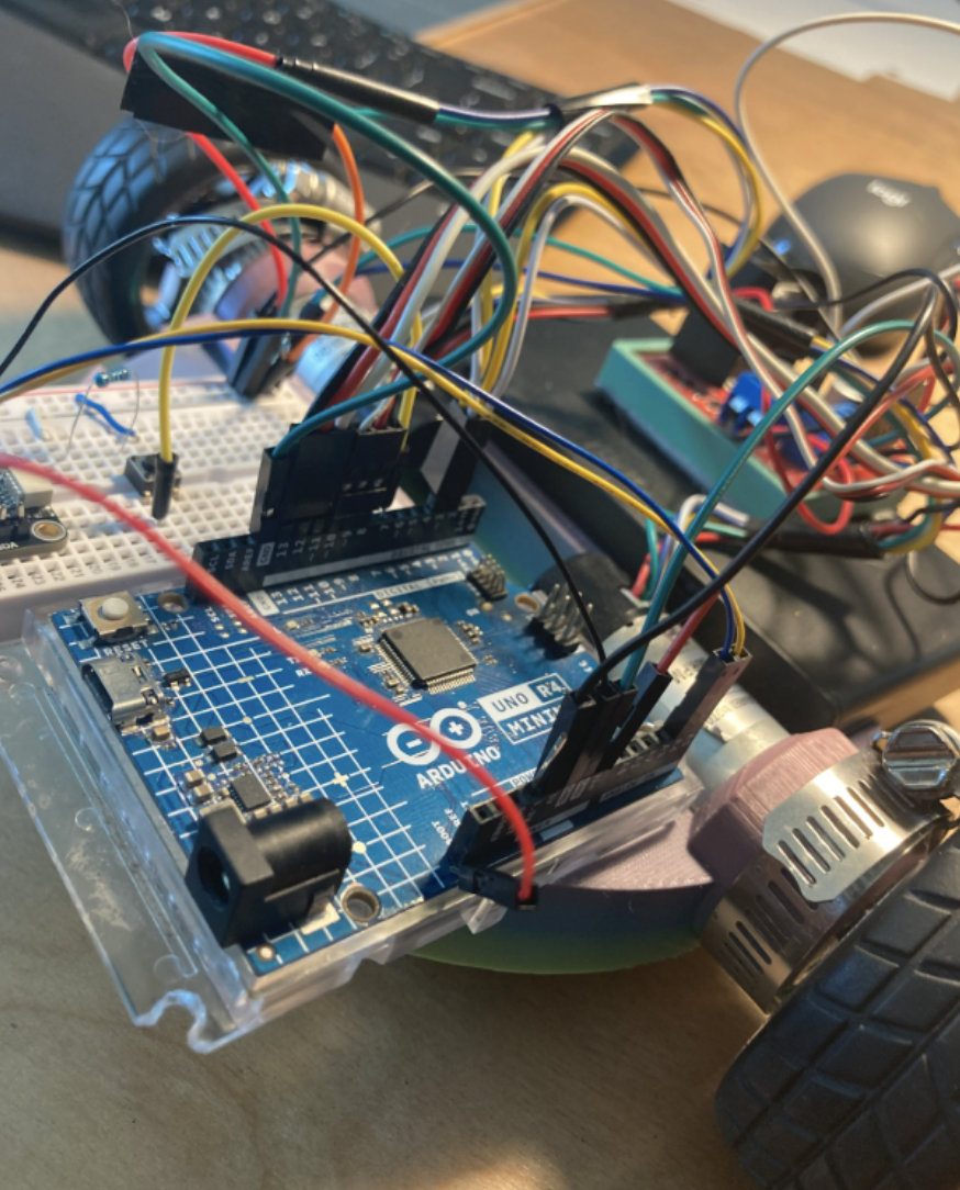
We replaced the continuous servos with my old encoders, but needed a new chassis as our current one was now too small. I resurrected my previous design from the 2024-2025 season. Here is a picture with the chassis outfitted with the components:
Additionally we have added the MPU6050. The MPU is a gyrometer and accelerometer. We used it to check the orientation of the robot to make sure we were turning 90 degrees and moving in a straight line. It was largely successful due to the finicky reading of the MPU. It drifted a lot when trying to read. We also were unable to read the MPU and the encoder motors at the same time due to the limited abilities of the Arduino. Without reading the encoders we attempted to just try and have the robot move in a straight line using readings from the MPU but it was not fruitful.
December 2025 (the first half)
We made several major changes to the robot in December. First we upgraded the MPU to a BNO055. Secondly we had been using code that read both encoder pins and attempted to discern the direction of the movement and update a count of how far we had traveled ever since I had used it in Electric Vehicle back in 2024. We wanted to read the BNO while also being able to read the encoder motors. Since the Arduino cannot multi-thread, we explored the possibility of using an ESP32 but were reluctant to abandon our faithful Arduino. Instead we found out about interrupts. Using interrupts to read the encoders in the background the Arduino was freed up to respond to feedback from the BNO. This was our first successful implementation of a feedback loop. It is quite laughable that it took me a year and a half to finally reach this point.
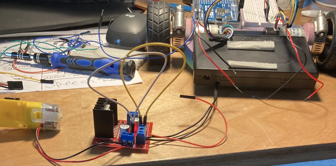
However we unfortunately found that one of the pins needed to read the encoders was also used by
the Arduino rev3 motor driver for some other function. This meant that we would be only able to
read one encoder. This was not a viable situation so as you can see from the image above we
resorted to using a L298n motor driver to free up the Arduino’s Interrupt Pins. This was our new circuit:
December 2025 (the second half)
The BNO055 was both a life saver and the single one component that broke our brains.
It behaved erratically at first. We were able to use an Adafruit Library to read most of
our information from the BNO. Initially we could not read any values from it except for
zeros. At some point we discover a small copper pad at the back of the breakout board
intended to be optionally used to change the I2C address from 0x28 (the default) to 0x29.
We thought that somehow we were connecting the copper pad by mistakenly and changing the
address making it impossible for the Arduino to receive data. Our theory was incorrect but
we didn’t realize this for quite a while. We explored several possibilities for why it was malfunctioning:
The address of the BNO055 accidentally changes at some point during usage making
it unreachable. The default I2C address is 0x28 but can be changed to 0x29 according to
Adafruit’s product page. We are using the I2C address because we are making use of the
STEMMA QT connector from Adafruit instead of using the default serial communication.
According to this forum the address changes when the VIN (input voltage) is at a
certain level. If the VIN is 3V or 3.3V? The address changes to 0x29. When the VIN
is 5V the address defaults to 0x28. Additionally the BNO055 resets when it either
receives a pulse on its RST pin or when the VIN drops below 0.7V according to this forum.
BNO055 lacks an "external crystal" which the Adafruit library assumes it has.
See issue #5 in Potential Causes from Research. According to Adafruit, who
made the breakout board, there is an external crystal. This means that we don’t have to worry about issue #5.
"...an external 32.768KHz crystal…" And this ReadME in a github project based on
the Adafruit library also backs this up. The BNO055 has a crystal both from the
Adafruit board and the Bosch chip. The external crystal from the Adafruit board
is supposed to make it more stable. There is a way to confirm that the board has
an external crystal using an oscilloscope but we have not tested this.
BNO055 is being put into CONFIG mode. See this arduino forum and this adafruit forum
Most of these issues were not related to our specific problem. In the end after observing when we would bloc
k the Arduino until the Serial Connection had opened we realized that the BNO was functioning properly.
This brought us to the conclusion that the BNO needed more time to calibrate before being used.
We were partially correct. After a couple successful test runs,
it broke again. We did some more research and found out that the Arduino R4 somehow
had a hard time communicating with the BNO because of the operating frequency of the
two components. We had two options: 1 use an Arduino R3 (which supposedly lacked this
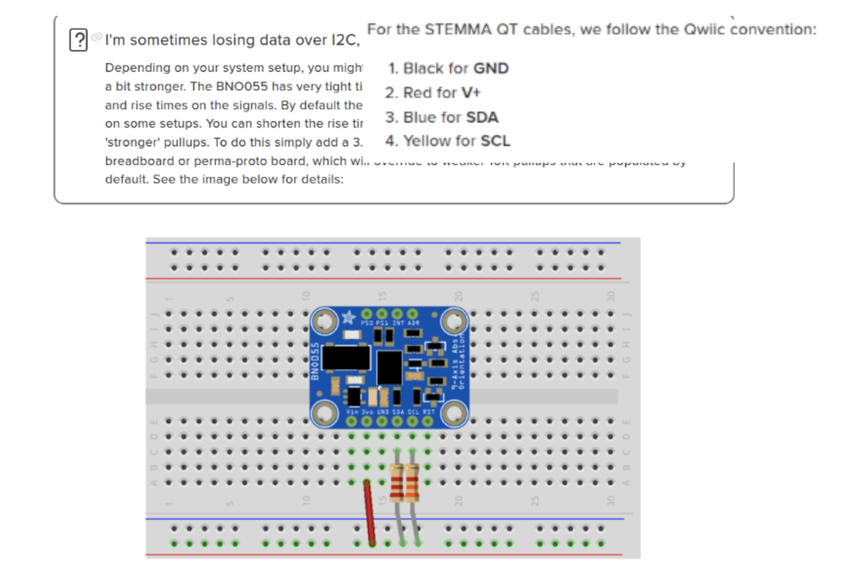
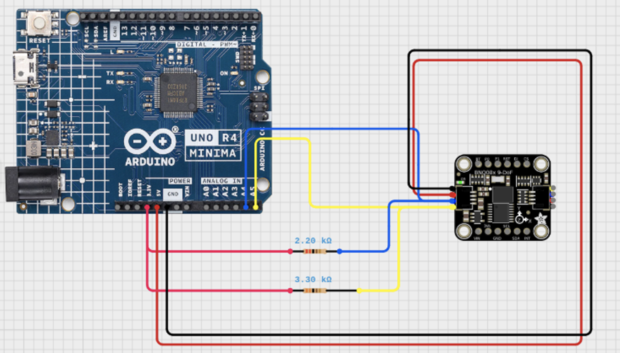
timing issue) or 2 add some pullup resistors to "shorten the rise times." This is based on this comment:
We rewired the SCL and SDA jumpers like so:
Now our use procedure is to:
Upload the code to the Arduino
Open Serial and what for it to print that it has finished void setup()
Reset the robot via the reset button on the Arduino.
Open Serial again and wait for it to print that it has finished setting up
Uplug laptop from the Arduino
Run via pushbutton
At this point the Arduino does not need code reuploaded. Seems to work consistently from this point on. Even after powering the system down. With the BNO functioning we were able to successfully implement a feedback loop that allows us to course correct to a straight line. Also used in turning until we had reached a certain orientation. We finished the month with this design:
March 2026
The regional competition we attended was on March 7th.
Unfortunately due to some misplaced confidence we were unable
to complete a single successful run. The primary issues that held us back from medaling where:
Didn't adequately test BNO055 before running
On our final run the BNO055 failed to calibrate causing the robot to lose course correction and the ability to turn.
Uploading code before aligning with the course
This caused the robot to set its original orientation in a way that was not relative to the course causing the robot to complete the route we had planned just not on the course.
Some secondary issues that came up were that the proctor found it difficult to measure the distance from the pencil to the target point due to the chassis obscuring a clear view.
Thankfully among other things we did not get tiered and the team was able to make it to the State competition.
To address the issues we have created a new chassis that allows an easier line of sight of the pencil for the proctor, and are still developing a competition checklist and manual testing for the BNO055 to mitigate any human error.
April 2026
State competition is in a couple weeks. We have made a new chassis and have pin pointed the issue with the BNO055. Turns out the i2c bus was locking up because of pullup resistors stretching the clock. This can be solved by completing the transmission via the scl cable and therefore releasing the slave which opens the sda cable back up.
We have developed a checklist for use when testing and running the competition.
As we dug deeper into the BNO055 issue we found that there are some pretty big
timing problems that are exacerbated by using the Arduino r4. These can be ameliorated
slightly by stretching the clock and constantly testing the connection and recovering.
However we found that this would interfere with running the course in the manner we
intended coupled with the fact that we lose points for stalling (recovering the BNO055
is timely and could be interpreted as stalling). Thus instead of implementing these changes
we chose to switch the r4 out for the r3 model which doesn’t have these timing issues. So far
in testing we have observed no issues when running with some minor clock stretching.
SOFTWARE AND HARDWARE DEEP DIVE
SOFTWARE:
Code Overview
In our code we implement a basic feedback loop. We read information from our sensors (the encoders and BNO055). We take this information or feedback and use that to dictate the decisions made by the robot.
Functions used in code:
setup(void) - default Arduino function, used to start the BNO055 communications and setup pinmodes and interrupt pins.
update_count_A(void) - updates the volatile global variable that stores the number of ticks (parts of a rotation) covered by motor A
update_count_B(void) - updates the volatile global variable that stores the number of ticks (parts of a rotation) covered by motor B
wrap(int angle) - “wraps” any angle or orientation to be between 0 degrees and 359 degrees. For example if I wanted the robot to turn to 470 degrees the robot would be unable to do this because the BNO055 only reads values from between 0 and 359 degrees. Therefore with the wrap() function I can “wrap” 470 degrees to 110 degrees using simple algebra.
round_angle(int angle) - takes an angle and rounds to either 0, 90, 180, or 270 degrees depending on its proximity to said angles. Its purpose is to deal with a minor issue of when the robot is at 0 degrees the BNO055 drifts slightly and reads 359 degrees. This causes the robot to refuse to turn because the conditions for turning have already been reached.
turn_motor(motor, direction) - used to communicate to the motor driver which motor (A or B) needs to turn clockwise or counter-clockwise
stop(void) - tells the motor driver to cut power supply to motors and also sets the directional pins (used to control which direction the motor is turning) to zero. Effectively this function stops the robot. It should be noted that this does not “stop” the motors as in the sense that a brake on a car does. The motor can still freely rotate. This means that when traveling at high speeds and then stopping suddenly you should expect to see skidding.
turn_right(void) - Turns the robot 90 degrees to the right. We read the BNO055 to find our current orientation. Then we calculate what the angle we are turning to will be. This angle is our target. We then proceed to turn until we have reached said target angle. We use some simple math and the wrap() function to watch the angles read from the BNO055 fulfill the condition. Doing this in this way allows us to only need one condition for turning from any orientation instead of having to program separate cases for turning to 0, 90, 180, and 270 degrees.
turn_left(void) - Similar execution of the process in turn_right(void). The only big difference is that the conditions for turning to the target angle are different due to the fact that we approach it from a different direction.
forward(target) - Moves the robot forward a distance of target ticks (increments of the motor completed). In the turning functions we solely made use of the BNO055 readings. In this function we also use the encoders. We access the distance we have covered via the volatile globals Count_A and Count_B. These are updated via interrupts connected to the encoders. When the encoder moves it the arduino updates the count variables in the background because of this we can constantly check that we are going straight while also tracking how far we have gone.
Backward(target) - This is the same as forward() function but the course correction element is adjusted to compensate for the fact that we are moving backwards. If we had not adjusted the course correction it would have resulted in the robot going in circles forever because it knows that it is not going straight but it can’t correct.
loop(void) - default Arduino function. We use it to write our instructions for solving the maze using the movement function
UNUSED accelerate(void) - was originally used to accelerate and decelerate to ease starting and stopping. Untested and unused due to the fact that we couldn’t figure out how to write it without using blocking functions that would “block” our background processes of reading the encoders
Moving Straight
If you have never made a robot then you may not know the frustration of putting time and effort into a buggy or car and when you turn it on it literally cannot move in a straight line. I mean how hard can it be? Actually it is really hard. At least for me…
Course correction uses the BNO055 to tell us whether we are in a straight direction or have started to veer off to the side. With this feedback we can adjust the tilt of the robot in motion. This looks like speeding up one motor over the other. The robot begins to turn back into the correct orientation. Once we have reached our original heading we stop correcting. However due to the imperfect nature of the motors once we start course correcting we do not stop correcting until we have reached our target distance.
Reading the BNO055
Reading the BNO055 was a long and difficult process. We used the breakout board from Adafruit and subsequently used the Stemma QT connection provided. We also used the Adafruit library for the Arduino to read the values. However after frequent use the BNO055 would only return zeros. It was incredibly frustrating. We were using an Arduino R4. Supposedly this microcontroller has something different about it that messes with the setup and rise timing on the I2C bus when reading the SCL and SDA pins. The Adafruit breakout board has default 10k resistor pullups. By increasing the resistance on the pullups we can lengthen the setup and rise times for the BNO055. We added a 3k resistor to the SCL and a 2k resistor to the 2k pullup on the SDA line. This fixed our issue with the BNO055. We give it around 2 seconds of setup time and then begin reading almost immediately.
Reading Encoders
Reading the Encoders accurately is really important. You don’t want to miss anything because it can cause you to go too far or too short. Since we are giving most of our attention to reading the BNO055 to course correct we can’t really read the encoders at the same time. We have two processes or loops that need to be followed in parallel. The Arduino R4 unfortunately cannot run tasks in parallel. Well not in the way that you would conventionally. Using what are called interrupts we can use minimal processing power to read the encoder values. Every time the encoder tracks movement it sends a signal to the arduino. We have them connected to pins 2 and 3. These pins are interrupt pins and can perform simple math in the background. We can use the interrupt pins to update a global volatile integer. Now while we are course correcting as we move though the loop we can check the number of movements we have made and figure out how far we have moved without having to divert our attention between two processes.
HARDWARE
The hardware we used on the robot is fairly easy to come by.
We use the Arduino Rev 4 microcontroller. This is the brain of
the robot. It holds our instruction set and tells the other
components what to do. Our motor driver or the translator from microcontroller
to motors is the L298n. It is a widely produced motor driver that is very cheap.
You can actually make your own at home if you have the patience! We use rotary encoders
that make use of the Hall effect to measure distance. I have seen the encoders that work
with a photogate. I think that the Hall effect motors are more precise, but if you don’t
have the budget the photogate style encoders are great too. We picked rather slow motors
for our project at only 150 rotations per minute max speed. This is advantageous to us
because as we increase in speed we become less accurate however as our robot becomes more
adaptable we are beginning to feel the need for faster motors. If you buy high RPM motors
(for example most hobby motors are ~1000 RPM) you will notice that when you have low voltage
levels the motor will struggle or even burn out. The crowning jewel of the robot is our BNO055.
This is really what makes the robot able to even be competitive. In combination with the rotary
encoders they are the eyes and hands of the robot. Without them our robot would move blindly without
knowing where it was. Our power supply is from an 8 pack of AA batteries as per the regulations in the
rules. The chassis is 3D printed. To manipulate the water bottle we have a pair of prongs that fit closely
around the bottle that extend from the chassis. Besides this we have a breadboard installed on the chassis
to allow us to use a small push button and experiment with the pullup resistors for the Stemma QT connection
with the BNO055.